Difference between revisions of "Numerical Analysis of Interference Patterns"
| (35 intermediate revisions by 2 users not shown) | |||
| Line 1: | Line 1: | ||
| − | This page is currently a work in progress. | + | <font color="red">This page is currently a work in progress!</font> |
| − | + | [[Image:fringe_ex.jpg|thumb|An Example of a Closed Fringe Pattern]] | |
| + | Fringe pattern analysis methods can be sorted into two main categories: "temporal (phase shifting) methods and spatial methods." [[#References|[1]]] According to Kieran G. Larkin, interferogram analysis finds its roots in the 1960's from the work of Carre, Rowley and Harmon, who pioneered the use of former of the two methods described above. However, this form of analysis was problematic in that the phase shift needed to be precisely calculated (i.e. a large degree of experimental control must be present). This problem resulted in a wave of spatial analysis methods which took advantage of using single fringe patterns to obtain the necessary surface information. With experimental control and computing power increasing, current methods of fringe pattern analysis involve utilizing combinations of both experimental and computer based algorithms to produce more accurate results than were previously attainable [[#References|[1]]]. | ||
| + | |||
| + | The list below of analysis methods only represents a fraction of the variations of interferogram analysis (i.e. this list should not be considered exhaustive, but rather an overview of the main classes of analysis methods). | ||
== Phase Shifting Technique == | == Phase Shifting Technique == | ||
| − | [[Image: | + | [[Image:framediff.jpg|thumb|A schematic of rotations]] |
| − | As noted in the introduction, the first phase-shifting algorithms were designed in the 1960's by Carre, Rowley and Harmon. The essence of the phase shifting algorithm lies in the ability to gather the necessary phase information from (theoretically) three to (more realistically) five interference patterns, called frames, so that a nearly complete | + | As noted in the introduction, the first phase-shifting algorithms were designed in the 1960's by Carre, Rowley and Harmon. The essence of the phase shifting algorithm lies in the ability to gather the necessary phase information from (theoretically) three to (more realistically) five interference patterns, called frames [[#References|[1]]], so that a nearly complete surface topology may be rendered. |
| − | In recent years combinations of spatial and temporal methods have been combined and thus form a subcategory of the phase-shifting method, known as "self calibrating | + | In recent years combinations of spatial and temporal methods have been combined and thus form a subcategory of the phase-shifting method, known as "self calibrating spatio-temporal algroithms" [[#References|[1]]]. Among these methods are the Fourier Method, the Lissajou ellipse fitting method, the interferogram correlation method and others. Each of these possess strengths and weaknesses, mostly stemming from either the type of surface they best work for or the the number of frames required. |
| − | + | In his paper, Larkin proposes a method mentioned in the previous paragraph that utilizes a "truly isotropic 2-D Hilbert-Fourier demodulation algorithm" or "vortex algorithm" as a solution to the problem of overcoming discontinuities in un-processed fringe patterns. Larkin's algorithm initially eliminates the presence of the offset term a(x,Y) in the general fringe-pattern equation and follows by introducing a weighting function that depends on the frequency of the fringe oscillation. Thus, higher frequency areas of the pattern are weighted closer to zero, while those that are closer to DC receive a higher weight. This tactic, when combined with the vortex transform, gives one the ability to link different frames to analyze a fringe pattern, with as little as three separate images [[#References|[1]]]. | |
| − | |||
| − | |||
== Fourier Analysis Method == | == Fourier Analysis Method == | ||
[[Image:mexicanhat.jpg|thumb|A "Mexican Hat" function. (courtesy of [http://www.vector.org.uk/archive/v194/finn194.htm])]] | [[Image:mexicanhat.jpg|thumb|A "Mexican Hat" function. (courtesy of [http://www.vector.org.uk/archive/v194/finn194.htm])]] | ||
| − | |||
| − | |||
| − | |||
| − | |||
| − | |||
| − | |||
| − | [2] | + | The Fourier Analysis method of interferograms was created in 1982 by M. Takeda, H. Ina and S. Kobayashi and originally intended as an alternative to Moire Topography and the phase-shifting technique [[#References|[2]]],[[#References|[3]]] . However, this method was ineffective at analyzing closed fringe patterns. A revision to the method, solved this problem by utilizing a Cartesian to polar coordinate transform [[#References|[4]]]. The result of which could then be analyzed using the original method proposed. |
| − | [ | + | The revised Fourier Analysis method does have several limitations. The first requirement is that the "measurement wave front be a monotonic function in the direction of the carrier frequency" [[#References|[4]]]. For instance, if the surface resembling the Mexican hat function shown above were analyzed by the revised Fourier Analysis method, the result would look no different than a surface that decreased or increased from top to bottom. In order to analyze a fringe pattern generated by such a surface, an additional fringe pattern giving the carrier frequency must be used. |
== Regularization Algorithms== | == Regularization Algorithms== | ||
| − | The regularization method was created for the specific purpose of automatically demodulating "noisy" fringe patterns without any further unwrapping of the phase. Regularization algorithms involve evaluating the estimated phase field with a cost function against the actual pattern and then imposing the smoothness criterion. This method is repeated for each pixel on the phase field, until a global minimum is reached in the cost function. | + | The regularization method was created for the specific purpose of automatically demodulating "noisy" fringe patterns without any further unwrapping of the phase. Regularization algorithms involve evaluating the estimated phase field with a cost function against the actual pattern and then imposing the smoothness criterion. This method is repeated for each pixel on the phase field, until a global minimum is reached in the cost function [[#References|[5]]],[[#References|[6]]]. |
| − | Variations of the regularization method involve demodulating certain points in the low frequency region of the fringe pattern. This point can then be used to seed the estimated phase field. The algorithm then follows | + | Variations of the regularization method involve demodulating certain points in the low frequency region of the fringe pattern. This point can then be used to seed the estimated phase field. The algorithm then follows somewhat analogously to crystal growing. |
A drawback to this method arises from the fact "that a low-pass filtering and a binary threshold operation are required." | A drawback to this method arises from the fact "that a low-pass filtering and a binary threshold operation are required." | ||
| − | + | == Artificial Neural Network Method == | |
| − | + | [[Image:annschem.jpg|thumb|A schematic of the interactions between artificial neurons]] | |
| − | == | + | The human brain is composed of nearly 5 billion neurons, each of which have the simple job of receiving, integrating and transmitting of nerve pulses. From these simple functions neurons give rise to the functionality of the brain. The same principle was postulated in the 1940's by McCulloch and Pitts who theorized that a similar approach could be applied to computing [[#References|[7]]]. |
| − | |||
| − | |||
| − | + | Using a network of simple computerized "neurons" one might be able to mimic the brain and thereby create complex behavior from simple components. Differing from most computer-based programs, artificial neural network software requires a learning phase to adapt itself to the problem that it will be undertaking. The neurons are arranged in such a fashion that they are placed into three main categories: input, hidden and output neurons. After their creation, the network of neurons is trained under one of thre main training regiments: supervised, reinforced or unsupervised learning. Supervised learning results from constant feedback being given to the neural network during the training sequence. Reinforced learning can be defined by the use of simple "good" and "bad" remarks to the program after each "run." A neural network with unsupervised learning recieves no feedback from the "trainer." Given time constraints and the desire for a reasonable output, supervised or reinforced learning schedules are usually adopted and thus for a given input "weights" are given to guide the neurons "reaction" for a given stimulus[[#References|[7]]]. | |
| − | |||
| − | |||
| − | |||
| − | |||
| − | The | + | This method can either involve a system of many neurons linked together to analyze an entire image, or a small number of neurons can be analyze the image section by section. The former required both a long learning period and a large number of neurons, thus it is both computationally expensive and time intensive. The latter given a relatively slow rate processor and a section of six pixels and 36 neurons in total can analyze in 0.5s. This was demonstrated by Tipper, et al and was shown to be more effective than the Fourier transform method and Schafer's algorithm [[#References|[7]]]. |
== Genetic Algorithm == | == Genetic Algorithm == | ||
| − | + | <font color="red"> More to come on this subject! </font> | |
| − | + | [[#References|[3]]],[[#References|[8]]] | |
| − | + | ||
| + | <table> | ||
| + | <tr><td>[[Image:WFPDDia.jpg|thumb|A diagram of the Windowed Fringe Pattern Demodulation algorithm]]</td><td>[[Image:predividedFP.jpg|thumb|A pre-divided fringe pattern]]</td><td>[[Image:dividedFP.jpg|thumb|A partitioned fringe pattern]] | ||
| + | </table> | ||
== Simulated Annealing == | == Simulated Annealing == | ||
| + | <font color="red"> More to come on this subject! </font> | ||
| − | + | == References == | |
| − | |||
| − | === | ||
| − | |||
| − | |||
| − | |||
| − | |||
| − | |||
| − | |||
| − | |||
| − | |||
| − | |||
| − | |||
| − | |||
| − | |||
| − | |||
| − | |||
| − | |||
| − | |||
| − | |||
| − | |||
| − | |||
| − | |||
| − | |||
| − | |||
| − | |||
| − | |||
| − | |||
| − | |||
| − | |||
| − | |||
| − | |||
| − | |||
| − | |||
| − | |||
| − | |||
| − | |||
| − | |||
| − | + | <div class="references-small"> | |
| + | 1. K. Larkin, ''A self-calibrating phase-shifting algorithm based on the natural demodulation of two-dimensional fringe patterns'', University of Sydney, 2006. | ||
| − | + | 2. M. Takeda, H. Ina and S. Kobayashi; ''Fourier-transform method of fringe-pattern analysis for computer-based topography and interferometry'', University of Electrocommunications, 1982. | |
| − | + | </div> | |
| − | |||
| − | + | 3. F. Cuevas, J. Sossa-Azuela, and M. Servin; ''A parametric method applied to phase recovery from a fringe pattern based on a genetic algorithm'', 2002. | |
| − | + | 4. Z. Ge, F. Kobayashi, S. Matsuda, and M. Takeda; ''Coordinate-transform technique for closed-fringe analysis by the Fourier-transform method'', 2001. | |
| − | + | 5. M. Servin, J. Marroquin, and F. Cuevas; ''Demodulation of a single interferogram by use of a two-dimensional regularized phase-tracking technique'', 1997. | |
| + | 6. M. Servin, J. Marroquin, and F. Cuevas; ''Fringe-follower regularized phase tracker for demodulation of closed-fringe interferograms'', 2001. | ||
| − | + | 7. D. Tipper, D. Burton, M. Lalor; ''A neural network approach to the phase unwrapping problem in fringe analysis'', 1995. | |
| − | |||
| − | |||
Latest revision as of 20:43, 16 January 2008
This page is currently a work in progress!
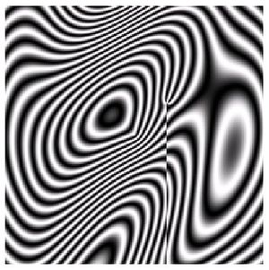
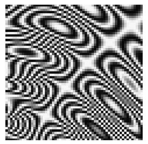
Fringe pattern analysis methods can be sorted into two main categories: "temporal (phase shifting) methods and spatial methods." [1] According to Kieran G. Larkin, interferogram analysis finds its roots in the 1960's from the work of Carre, Rowley and Harmon, who pioneered the use of former of the two methods described above. However, this form of analysis was problematic in that the phase shift needed to be precisely calculated (i.e. a large degree of experimental control must be present). This problem resulted in a wave of spatial analysis methods which took advantage of using single fringe patterns to obtain the necessary surface information. With experimental control and computing power increasing, current methods of fringe pattern analysis involve utilizing combinations of both experimental and computer based algorithms to produce more accurate results than were previously attainable [1].
The list below of analysis methods only represents a fraction of the variations of interferogram analysis (i.e. this list should not be considered exhaustive, but rather an overview of the main classes of analysis methods).
Phase Shifting Technique
As noted in the introduction, the first phase-shifting algorithms were designed in the 1960's by Carre, Rowley and Harmon. The essence of the phase shifting algorithm lies in the ability to gather the necessary phase information from (theoretically) three to (more realistically) five interference patterns, called frames [1], so that a nearly complete surface topology may be rendered.
In recent years combinations of spatial and temporal methods have been combined and thus form a subcategory of the phase-shifting method, known as "self calibrating spatio-temporal algroithms" [1]. Among these methods are the Fourier Method, the Lissajou ellipse fitting method, the interferogram correlation method and others. Each of these possess strengths and weaknesses, mostly stemming from either the type of surface they best work for or the the number of frames required.
In his paper, Larkin proposes a method mentioned in the previous paragraph that utilizes a "truly isotropic 2-D Hilbert-Fourier demodulation algorithm" or "vortex algorithm" as a solution to the problem of overcoming discontinuities in un-processed fringe patterns. Larkin's algorithm initially eliminates the presence of the offset term a(x,Y) in the general fringe-pattern equation and follows by introducing a weighting function that depends on the frequency of the fringe oscillation. Thus, higher frequency areas of the pattern are weighted closer to zero, while those that are closer to DC receive a higher weight. This tactic, when combined with the vortex transform, gives one the ability to link different frames to analyze a fringe pattern, with as little as three separate images [1].
Fourier Analysis Method
The Fourier Analysis method of interferograms was created in 1982 by M. Takeda, H. Ina and S. Kobayashi and originally intended as an alternative to Moire Topography and the phase-shifting technique [2],[3] . However, this method was ineffective at analyzing closed fringe patterns. A revision to the method, solved this problem by utilizing a Cartesian to polar coordinate transform [4]. The result of which could then be analyzed using the original method proposed.
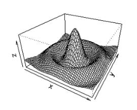
The revised Fourier Analysis method does have several limitations. The first requirement is that the "measurement wave front be a monotonic function in the direction of the carrier frequency" [4]. For instance, if the surface resembling the Mexican hat function shown above were analyzed by the revised Fourier Analysis method, the result would look no different than a surface that decreased or increased from top to bottom. In order to analyze a fringe pattern generated by such a surface, an additional fringe pattern giving the carrier frequency must be used.
Regularization Algorithms
The regularization method was created for the specific purpose of automatically demodulating "noisy" fringe patterns without any further unwrapping of the phase. Regularization algorithms involve evaluating the estimated phase field with a cost function against the actual pattern and then imposing the smoothness criterion. This method is repeated for each pixel on the phase field, until a global minimum is reached in the cost function [5],[6].
Variations of the regularization method involve demodulating certain points in the low frequency region of the fringe pattern. This point can then be used to seed the estimated phase field. The algorithm then follows somewhat analogously to crystal growing.
A drawback to this method arises from the fact "that a low-pass filtering and a binary threshold operation are required."
Artificial Neural Network Method
The human brain is composed of nearly 5 billion neurons, each of which have the simple job of receiving, integrating and transmitting of nerve pulses. From these simple functions neurons give rise to the functionality of the brain. The same principle was postulated in the 1940's by McCulloch and Pitts who theorized that a similar approach could be applied to computing [7].
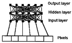
Using a network of simple computerized "neurons" one might be able to mimic the brain and thereby create complex behavior from simple components. Differing from most computer-based programs, artificial neural network software requires a learning phase to adapt itself to the problem that it will be undertaking. The neurons are arranged in such a fashion that they are placed into three main categories: input, hidden and output neurons. After their creation, the network of neurons is trained under one of thre main training regiments: supervised, reinforced or unsupervised learning. Supervised learning results from constant feedback being given to the neural network during the training sequence. Reinforced learning can be defined by the use of simple "good" and "bad" remarks to the program after each "run." A neural network with unsupervised learning recieves no feedback from the "trainer." Given time constraints and the desire for a reasonable output, supervised or reinforced learning schedules are usually adopted and thus for a given input "weights" are given to guide the neurons "reaction" for a given stimulus[7].
This method can either involve a system of many neurons linked together to analyze an entire image, or a small number of neurons can be analyze the image section by section. The former required both a long learning period and a large number of neurons, thus it is both computationally expensive and time intensive. The latter given a relatively slow rate processor and a section of six pixels and 36 neurons in total can analyze in 0.5s. This was demonstrated by Tipper, et al and was shown to be more effective than the Fourier transform method and Schafer's algorithm [7].
Genetic Algorithm
More to come on this subject! [3],[8]
Simulated Annealing
More to come on this subject!
References
1. K. Larkin, A self-calibrating phase-shifting algorithm based on the natural demodulation of two-dimensional fringe patterns, University of Sydney, 2006.
2. M. Takeda, H. Ina and S. Kobayashi; Fourier-transform method of fringe-pattern analysis for computer-based topography and interferometry, University of Electrocommunications, 1982.
3. F. Cuevas, J. Sossa-Azuela, and M. Servin; A parametric method applied to phase recovery from a fringe pattern based on a genetic algorithm, 2002.
4. Z. Ge, F. Kobayashi, S. Matsuda, and M. Takeda; Coordinate-transform technique for closed-fringe analysis by the Fourier-transform method, 2001.
5. M. Servin, J. Marroquin, and F. Cuevas; Demodulation of a single interferogram by use of a two-dimensional regularized phase-tracking technique, 1997.
6. M. Servin, J. Marroquin, and F. Cuevas; Fringe-follower regularized phase tracker for demodulation of closed-fringe interferograms, 2001.
7. D. Tipper, D. Burton, M. Lalor; A neural network approach to the phase unwrapping problem in fringe analysis, 1995.
