Difference between revisions of "Temperature Control Program"
| Line 28: | Line 28: | ||
[[File:TempReg.jpg|200px|thumb|right|upright|Temperature Regulation Section centered on the GoUnlessTooHot2 VI.]] | [[File:TempReg.jpg|200px|thumb|right|upright|Temperature Regulation Section centered on the GoUnlessTooHot2 VI.]] | ||
| − | The initialization of the DAQ section leads directly into the temperature conversion and storage section. Here the voltage readings are converted to temperature in Fahrenheit with an equation block. The temperature values are then all merged into one wire connected to a waveform chart, which displays the temperatures separately on a line graph on the front panel. The combined signals are also sent to a user defined VI named TemperatureSpread, which stores the highest temperature out of all the signals in a variable called Highest Temperature. Each individual temperature value in fahrenheit is converted to celsius and displayed (in both fahrenheit and celsius) on the front panel. Additionally, each temperature in Fahrenheit is stored as a variable named after the location of its respective thermistor. These variables are combined and stored as one variable called WriteToFile (this section of the code is above the Initialization of the DAQ section at the time of this documentation). WriteToFile connects to a "save to measurement file" block, which | + | The initialization of the DAQ section leads directly into the temperature conversion and storage section. Here the voltage readings are converted to temperature in Fahrenheit with an equation block. The temperature values are then all merged into one wire connected to a waveform chart, which displays the temperatures separately on a line graph on the front panel. The combined signals are also sent to a user defined VI named TemperatureSpread, which stores the highest temperature out of all the signals in a variable called Highest Temperature. Each individual temperature value in fahrenheit is converted to celsius and displayed (in both fahrenheit and celsius) on the front panel. Additionally, each temperature in Fahrenheit is stored as a variable named after the location of its respective thermistor. These variables are combined and stored as one variable called WriteToFile (this section of the code is above the Initialization of the DAQ section at the time of this documentation). WriteToFile connects to a "save to measurement file" block, which is in a case structure that skips saving the data if there are zero or not a number (NaN) values coming from the DAQ. |
<br/><br/> | <br/><br/> | ||
Revision as of 22:59, 17 December 2015
Page by: Andrew Sampino. Logbook
The temperature control program is a LabView VI, which checks and regulates the temperature of the Fiber Heating Box. Once the program is initiated it will turn on the hotplate in the heating box and regulate the temperature until either the box gets dangerously hot or a user indicated stop condition has been met. The program outputs commands to a netbooter, which is the hotplate's voltage source, and reads inputs from thermistors through a DAQ (data acquisition unit). After a heating run the program will save the measured temperatures and the time at which they were measured to an excel file.
The front panel contains digital temperature and time displays, various controls to set parameters, and a waveform chart, which displays each temperature measurement over time.
Instructions for a Heating Run
In order to calibrate the communication between the DAQ and the computer, the program InstaCal must be used. Open up instacal and right click on the DAQ, then click configure and there will be a drop down menu called number of channels in which 8 single ended mode should be selected and not 4 differential. This doesn't need to be done before every run, but it should be checked if the program reports that the DAQ isn't responding. Next, the physical setup must be appropriately configured. To set the hotplate temperature, plug it into a regular wall outlet and turn the knob until the temperature display reads 140 degrees Celsius, then unplug it. Plug the hotplate into outlet one on the correct netbooter (usually the top one) as the state of this outlet will be controlled by the program. Finally, plug all fans in and look to see that they are actually spinning.
In order to perform a heating run there are a number of parameters, which can be found on the front panel, that must be set properly. The conditions for a normal run are listed below:
- Samples/Channel: 1 is sufficient here, increase for more data points.
- Rate: 1 is sufficient here, increase for more data points.
- Sample Mode: FiniteSamples
- Save your file?: Pressed to save the run, unpressed otherwise.
- STOP: Must be unpressed at program start.
- Control Manually: Automatic
- Target Temperature: 175
- Timed Heater Turn off: any desired time (in minutes).
- Start Timer: On to start timer when the program starts, off otherwise. *Can turn this on at any point during run.
Once all of these are set appropriately the run can begin. Pressing the LabView Run button on the tool bar will initiate all relevant processes and the hotplate will turn on within the first twenty seconds assuming the interior box temperature is less than the target temperature. When the netbooter is on and supplying voltage to the hotplate an indicator light on the front of the netbooter under "Power Outlet Status 1" will be on. If the program needs to be stopped in the middle of a run, the "STOP" button must be pressed; as a general rule do not end the program with the Abort Execution Labview button in the tool bar while the netbooter indicator light for outlet one is still on. If this does happen by accident, the program can be started again and the "STOP" button pressed while it is running.
Program logic
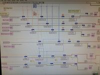
The overarching logic behind the program is to turn the hotplate off when the box is too hot and on when it is too cold. All of the code is contained in a sequence structure consisting of two frames. The first frame contains nearly all of the code and is what drives all operating functions, the second frame contains the sub VI HP 1 Outlet 1 OFF, which shuts off the netbooter's outlet one (and therefore the hotplate). A while loop contains all of the code in the first frame, which can be split up into four major groups of functional purpose: Initialization of DAQ interface, temperature conversion and storage, temperature regulation, and stop conditions.
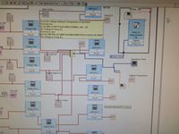
In the initialization of the DAQ section there is only one unique sequence of code, which is repeated six times, once for each analog input connected to a thermistor. The sequence begins (from left to right) with the specification of the desired analog channel; a drop down menu shows all available options. Then, the minimum and maximum voltages are set to -5V and 5V in accordance with DAQ parameters. Next, the sample rate and samples per channels are read from the controls on the front panel. The function "Start task" then allocates memory for interaction with the DAQ, which is used in the following function "Read". "Read" stores the voltage signals from the DAQ and outputs them to a conversion equation, which is part of the temperature conversion and storage section. Finally, the sequence ends by clearing allocated memory with "Clear task". There is also error propagation from the voltage setting through "Clear task" to a display, but this has no effect on the functionality of the sequence.
The initialization of the DAQ section leads directly into the temperature conversion and storage section. Here the voltage readings are converted to temperature in Fahrenheit with an equation block. The temperature values are then all merged into one wire connected to a waveform chart, which displays the temperatures separately on a line graph on the front panel. The combined signals are also sent to a user defined VI named TemperatureSpread, which stores the highest temperature out of all the signals in a variable called Highest Temperature. Each individual temperature value in fahrenheit is converted to celsius and displayed (in both fahrenheit and celsius) on the front panel. Additionally, each temperature in Fahrenheit is stored as a variable named after the location of its respective thermistor. These variables are combined and stored as one variable called WriteToFile (this section of the code is above the Initialization of the DAQ section at the time of this documentation). WriteToFile connects to a "save to measurement file" block, which is in a case structure that skips saving the data if there are zero or not a number (NaN) values coming from the DAQ.
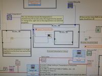
The temperature regulation section serves to keep the box at a prescribed temperature. Here the code is centered around a user defined VI named GoUnlessTooHot2, which reads the user indicated target temperature and turns the hotplate on if the highest measured temperature is more than one degree fahrenheit below that value and turns it off if the highest measured temperature is more than one degree higher than that value. GoUnlessTooHot2 also has failsafes that check if there are zero and NaN values reported from the variable Highest temperature and if the box temperature exceeds 190 degrees Fahrenheit. If either of these conditions are met the VI will shut the hotplate off with the use of the VI HP 1 Outlet 1 OFF. GoUnlessTooHot2 is contained in the true state of a case structure that is controlled by a connected timer, which returns true once every ten seconds; the result is that GoUnlessTooHot2 only reads values from the variable Highest Temperature every ten seconds. Therefore, the hotplate state can only change at a maximum frequency of once every ten seconds. Having both a time constraint and a temperature range is redundant so the time dependence of the case structure should be removed, but the case structure itself should be left in tact as it has another function related to stop conditions.
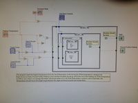
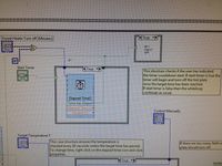
The stop condition section is not as localized as the the other sections because the three ways to manually stop the hotplate are independent of each other. The first method of stopping the hot plate is the STOP button, which is the stop condition for the overarching while loop in the first frame; this terminates the while loop and ends the first frame of the sequence structure. The second frame of the sequence structure will then begin and shut off the hotplate and the program will end. The second method is in the manual controls. These controls determine the state of a case structure in the VI GoUnlessTooHot2, which can automatically regulate the temperature, turn the hotplate on, or turn the hotplate off all without ending the program. The final method is a timed stop. The timer is an "elapsed time" block in the true state of a case structure, which is controlled by a boolean button. When the button is pressed the case structure is set to a true state and the timer runs until a user indicated amount of time passes. At this point the VI HP 1 Outlet 1 OFF is run and the temperature regulation section subverted to turn off the hotplate for the rest of the run.
