Difference between revisions of "SiPM Amplifier Signal Analysis"
Senderovich (talk | contribs) m |
Senderovich (talk | contribs) m |
||
| Line 2: | Line 2: | ||
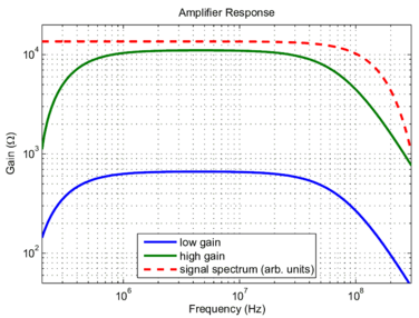
[[Image:AmpResp.png|thumb|376px|Amplifier's spectral response plotted together with the signal's spectrum.]] | [[Image:AmpResp.png|thumb|376px|Amplifier's spectral response plotted together with the signal's spectrum.]] | ||
| + | |||
| + | |||
| + | Since the tagging of the tagger microscope is set by the dead time of its sensors, shortening amplified pulses from the SiPMs is essential. However, a lower-bound requirement exists on the speed of the output signals: the ADC reading out microscope signals sampled at 250 MHz. | ||
| + | |||
| + | Photonique, the manufacturer of the 2 mm active area SiPMs adopted for this design, promises rise times <3 ns and cell recovery time <15 ns. The signal from the SiPM was measured with a laser diode - a device thought to have negligibly fast response. The light source was driven with an electronic pulse barely over threshold to generate very short signals on the order of a few photons in intensity. Undoing the convolution due to the relatively slow 200 MHz oscilloscope indeed yields a very short signal shown in the adjacent figure (smoothed and reasonably approximated by a Gaussian.) The shaping of this input signal by the modeled amplifier was then examined. | ||
| + | |||
| + | The speed of the amplifier response is one of the chief challenges. The transistors themselves, at a bandwidth of ~4 GHz, cover the expected signal spectrum well enough. However, points in the amplifier circuit where currents are injected present integrators with the RC time set by the effective AC coupling capacitance and input impedance of the following stage. Since reduction of effective capacitance at the SiPM circuit stage is not an option (the effective charge deposited per SiPM pixel discharge decreases) the input impedance was minimized. This is accomplished both in the amplifier and summing circuit input stages with injection on the transistor emitter (as opposed to base). The effective resistance is thus on the order of 20 Ω (generally quiescent current-dependent value) as opposed to βR<sub>E</sub> as would be seen looking into the base. | ||
Revision as of 05:50, 11 February 2009
Since the tagging of the tagger microscope is set by the dead time of its sensors, shortening amplified pulses from the SiPMs is essential. However, a lower-bound requirement exists on the speed of the output signals: the ADC reading out microscope signals sampled at 250 MHz.
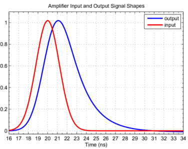
Photonique, the manufacturer of the 2 mm active area SiPMs adopted for this design, promises rise times <3 ns and cell recovery time <15 ns. The signal from the SiPM was measured with a laser diode - a device thought to have negligibly fast response. The light source was driven with an electronic pulse barely over threshold to generate very short signals on the order of a few photons in intensity. Undoing the convolution due to the relatively slow 200 MHz oscilloscope indeed yields a very short signal shown in the adjacent figure (smoothed and reasonably approximated by a Gaussian.) The shaping of this input signal by the modeled amplifier was then examined.
The speed of the amplifier response is one of the chief challenges. The transistors themselves, at a bandwidth of ~4 GHz, cover the expected signal spectrum well enough. However, points in the amplifier circuit where currents are injected present integrators with the RC time set by the effective AC coupling capacitance and input impedance of the following stage. Since reduction of effective capacitance at the SiPM circuit stage is not an option (the effective charge deposited per SiPM pixel discharge decreases) the input impedance was minimized. This is accomplished both in the amplifier and summing circuit input stages with injection on the transistor emitter (as opposed to base). The effective resistance is thus on the order of 20 Ω (generally quiescent current-dependent value) as opposed to βRE as would be seen looking into the base.

