FPGA Transceiver
Transceiver
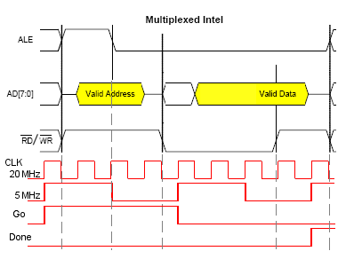
This block provides a level of abstraction between the precise CP2200/1 interface and a generalized interface seen by the internal blocks of the FPGA. This eliminates a need for the internal workings of the FPGA to be aware of the timing of the interface; hey simply order a start of transfer and wait for notification of the transfer's completion. The transceiver for its part initiates a read or write conversation with the CP2200/1 over the multiplex Intel bus upon request from the internals and returns data, if applicable, along with a "Done" pulse at the end of the conversation.
This unit serves as a bridge between the Ethernet Controller chip and the FPGA in terms of timing as well. The latter is run at the rate of its slowest client: the Temperature sensor which has a top recommended clock rate of 10 MHz. Given that CP2200/1 prefers 20 MHz, it was resolved that the FPGA will run on a 5 MHz clock subdivided from the Ethernet Controller's. The transceiver performs this subdivision and ensures data latching on the external and internal buses, as shown in the adjacent diagram.
I/O Pins
inputs
- fCLK: "fast" (20MHz) clock
- /Rst: asynchronous, active-low reset
- TxRx_Go: pulse to begin a transmission
- TxRx_RiW: read/write toggle: active-high read, active-low write
- TxRx_Ain: 8-bit bus for address to read to/write from
- TxRx_Din: 8-bit bus for data to write; ignored during a read
outputs to internals
- Done: pulse to signal completion of a transmission
R/W_out: read/write flag: active-high read, active-low writeA_out: 8-bit bus for address of last read/write- D_out: 8-bit bus for data of last read; internal systems should ignore for a write
- CLK : 5MHz clock for all internals subdivided from the master 20MHz clock.
outputs to CP2200/1
- /CS: active-low chip select
- MotEn: Motorola/Intel format toggle: active-high Motorola, active-low Intel
- MuxEn: Multiplexed flag; not used for CP2201
- ALE: ALE strobe
- /Wr: Active-low write flag
- /Rd: Active-low read flag
inouts
- AD: 8-bit address and data bus
